Blog


New Removable Cable Option for Acculevel Submersible Level Transmitter

April 15, 2024 | Product News

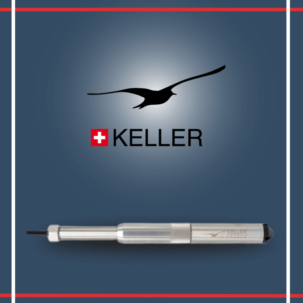
The KELLER America Acculevel and Acculevel SDI submersible level transmitters are now available with an optional Removable Cable. This option allows for the instrument to be separated from the cable for ease of installation and/or maintenance. The instrument with this option is equipped with a rugged connector that mates with a removable cable assembly, which is sold separately. The watertight seal is formed with the use of dual O-rings on the instrument and double O-rings on the removable cable assembly.

See datasheets here! 


How to Choose the Right Seismic Sensor for Your Application

April 4, 2024 | Product News

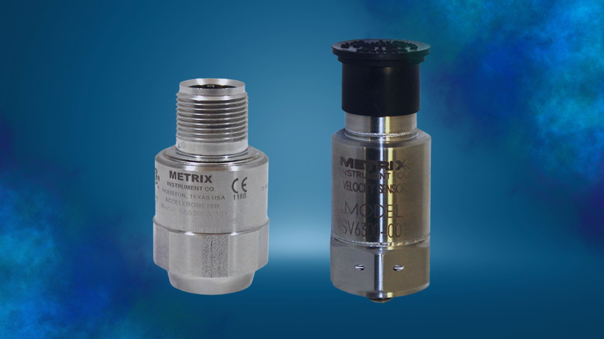
Choosing the right seismic sensor for your application – accelerometer or velocity sensor

In this blog post, we are discussing seismic sensors, which typically means we’re talking about machines with rolling element bearings. For machines with fluid film bearings, we typically use proximity sensors that can be augmented with casing mounted seismic sensors. At Metrix, we differentiate seismic sensors and seismic transmitters by the output needed by the monitoring or protection system. If the customer needs a 4-20 mA output, then a seismic transmitter will be used. Here we will be focused on seismic sensors, which provide a voltage output to a monitoring system. The seismic sensor outputs are in terms of acceleration or velocity, depending upon the machinery application needed. If the machine speed is 60 Hz or less, a velocity sensor is typically used. A velocity sensor is used because the bearing related, and rotor related, malfunction frequencies have the best signal to noise ratio. If the machine speed is greater than 60 Hz, then an accelerometer is typically used because it provides a better signal to noise ratio.

A seismic vibration sensor is inertially referenced, meaning that, if the sensor is not shaking, then the sensor will not produce a vibration output. Another way to say this is if you shake the seismic sensor on the earth or on the moon with the same force and frequency, you’ll get the same output. Seismic sensors are used to measure the motion of a casing of a rotating or reciprocating machine. The casing motion is usually indicative of the condition of the machine.

Seismic Sensors: General Considerations

Velocity Sensors

There are three basic types of velocity sensors, electromechanical, piezoelectric, and MEMS. An electromechanical velocity sensor uses a moving coil in the presence of a magnetic field to generate a voltage proportional to velocity, or the movement of the casing to which the velocity sensor is connected to. The piezoelectric velocity sensor takes advantage of the piezoelectric crystal inside, similar to an accelerometer, along with an integration and amplification circuit that converts the acceleration signal into a velocity signal. The MEMS (Micro-Electrical Mechanical Systems) velocity sensor takes advantage of the change in capacitance between small metal plates measured at the micro-millimeter scale. All these sensors have their advantages and disadvantages.

Even though the electromechanical velocity sensor has moving parts, its chief advantage over other velocity sensors is its ability to handle very high temperatures up to 375° C (707° F) without having to worry about melting integrated circuits. You see these types of sensors used on machines with relatively light casings and heavy rotors in high temperature environments, typically gas turbines.

The piezoelectrical velocity sensor is frequently used because of its solid-state design and its wide frequency range, typically from 2 Hz to 2,000 Hz. The piezoelectric velocity sensor is usually limited to 120° C (248° F). This velocity sensor does a great job at monitoring rolling element bearing machines that operate at 60 Hz or less. They’re also useful in measuring casing vibration on fluid film bearing machines when high temperatures are not encountered.

A MEMS velocity sensor is usually used for balance of plant equipment where a triaxial velocity sensor may be useful. The MEMS sensor can have a wide frequency range from 10 Hz to 5,000 Hz and is usually limited to 120° C (248° F). It should be understood that vibration is a ratio of forces to stiffnesses. A triaxial velocity sensor placed on top of the machine will not have the same X, Y, and Z axis readings as a triaxial velocity sensor placed horizontally on the machine due to the change in mechanical stiffness between the horizontal and vertical directions. For this reason, a single axis MEMS sensor can often provide more value when mounted properly on the machine.

Accelerometer Sensors

An accelerometer is a transducer that converts mechanical acceleration into an electronic signal. This is usually measured with a piezoelectric or MEMS device. The seismic sensors made from a piezoelectric material which produces a charge output proportional to acceleration (pC/g). When housed together with an electronic charge amplifier and charge-to-voltage converter (mV/g), it is referred to as an “internally amplified” accelerometer. If, due to temperature, only the sensor is machine mounted, the remote electronics are referred to as a “charge amplifier” (although it usually also contains a charge-to-voltage convertor). The MEMS accelerometer measures the acceleration by measuring the capacitance change between two surfaces. The output of the MEMS accelerometer is amplified and scaled to provide the same output as standard piezoelectric accelerometers.

Accelerometer sensitivity is a specification of the ratio of the accelerometer’s mechanical input to electrical output typically specified at a 100-Hz reference frequency or, as in the case of accelerometer frequency response, as a function of a range of frequencies.

Accelerometer frequency response is a specification of the accelerometer sensitivity as a function of frequency. Most accelerometers use the industry standard scale factor of 100mV/g or 10.2mV/m/s2. Accelerometers can have scale factors that range from 10 to 500 mV/g depending upon the sensitivity required. As the sensitivity increases, the frequency range increases. Typical frequency ranges for industry standard accelerometers are usually from 2Hz to 10kHz. Oftentimes the accuracy of the sensor is better at lower frequencies, like 2Hz to 5kHz, the accuracy may be +/- 5%. Whereas, from 2Hz to 10 kHz, the accuracy may be +/- 10%.

Summary

The above general guidelines should be helpful in determining whether to use a velocity sensor or accelerometer. One needs to consider the vibration frequencies of interest, the signal to noise ratio of a given sensor to the expected output, the environmental conditions, and mounting considerations. To learn more about this topic, also read our companion whitepaper titled “Accelerometers Versus Velocity Sensors – What’s the Difference?

All the advancements in sensors have been focused on precision, building in measurements on small scales that can give operators a better understanding of the trends that are taking place in their operations. Metrix sensors have been improved upon over the years to provide insight to identify how machinery vibration is changing over time, so you can schedule repairs and maintenance long before you must shut the machine down. For more information, please contact Neal Systems.
Resource


Application Note: Monitoring Methane at a Landfill

March 15, 2024 | Application NotesMunicipal: Water / Wastewater / Landfill

Flare System Retrofit A Turnkey Solution

Problem

Outdated Control System for Flare Operation

A landfill customer was in need of a new control system for their flare operation— a secondary disposal path for methane. Their current system was 20 years old, outdated, and remained dormant for 4 years.

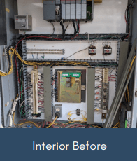
Their old panel had an obsolete circular chart recorder. Since their system was down for 4 years, NSI worked with them through the process of identifying potential roadblocks and old units that needed to be replaced.

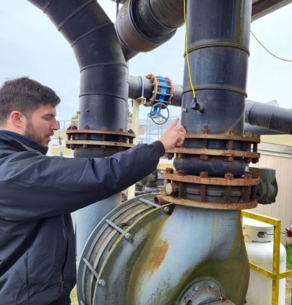
before
before interior
Resized-Resized-20230303-110350

Solution

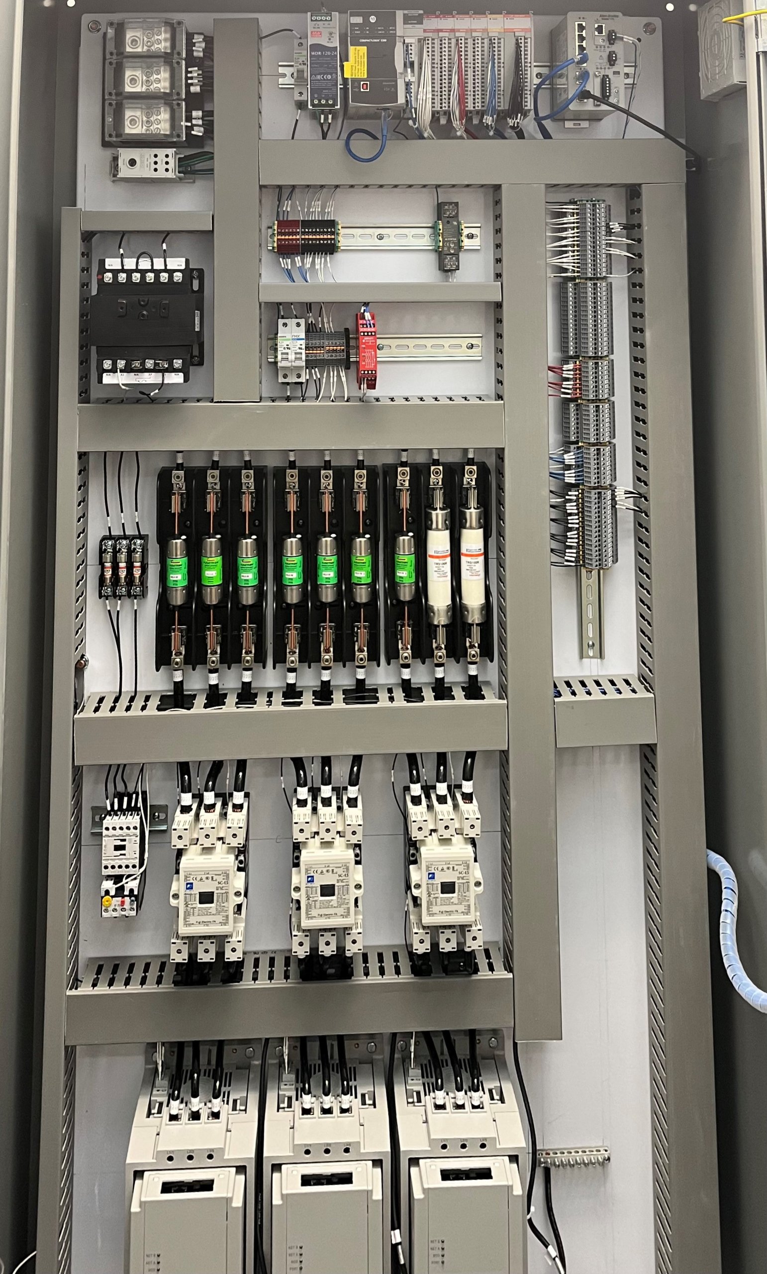
Neal Systems redesigned and retrofitted their old system with custom screens and newer technology, creating a cleaner, EPA compliant, operator interface.

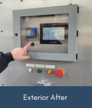
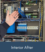
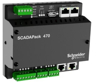
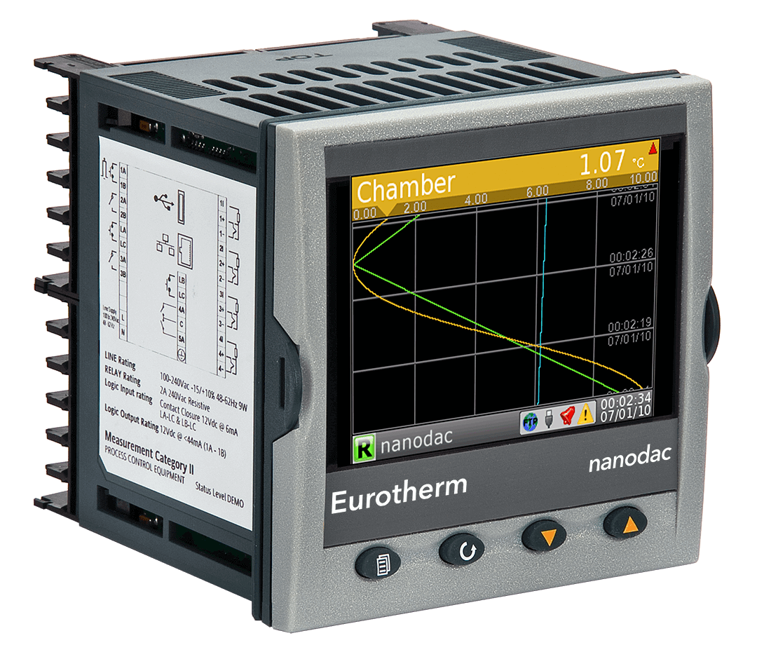
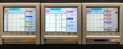
NSI retrofitted and rewired their current panel with Foxboro Scadapack 474 RTU and Eurotherm Nanodac for recording and PID loop control. The Scadapack 474 is ruggedized and able to operate in harsh environments, which makes it the perfect solution for outdoor operations.

exterior after
interior after

Conclusion

 
With Neal Systems’ solution, the landfill’s methane flare is operable and compliant with EPA regulations and recording requirements. The new solution provides the customer with reduced operator involvement in startup and operation. They can simply turn it on and forget about it. Our customer now has a viable secondary disposal path for methane in the event that their generators are unavailable.

Labor

Custom panel creation

Field Installation/Modification

Custom Engineering drawings

Integration with existing field devices

Trained staff and provided back-end support

Solutions Delivered

Cleaner/more intuitive and capable operator interface 

Easier data recording and storage

Custom screens for flare operation and maintenance Worked with customer to revive dormant system


Job Note: Wide Area Wireless Network Upgrade

March 15, 2024 | Application NotesMunicipal: Water / Wastewater / Landfill


Passaic Valley Sewerage Commission

Newark, NJ

Construction Costs: $30K


  •  
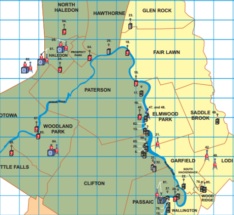
Passaic Valley Map -1

Services Provided

  • Wireless I/O Radio & Cellular Site Survey

  • Network Infrastructure Consultation

  • Data Acquisition Instrumentation Consultation

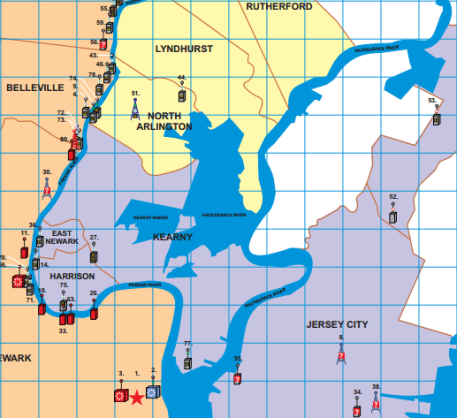
Passaic Valley Map -2

Wireless Communications Network Improves Sewage Plant Efficiency and Preparedness

Neal Systems supplied both hardware and engineering services to assist a major northern New Jersey wastewater treatment plant in designing, implementing, and integrating into the plant SCADA a wide area wireless communications network.


Consisting of more than 90 unlicensed 900 MHz and cellular I/O radios, the network linked together remote instrumentation stations within a municipal sewer system covering a region approximately 200 square miles in size. In addition to an I/O radio, each remote station contained instruments and sensors for measuring sewage flow, level, and toxicity levels at each of over 80 locations throughout the entire sewer system.


The wireless network delivered remote station data to the plant SCADA where operators could analyze it and take appropriate action to ensure the plant was adequately prepared to process the amounts of raw sewage the remote stations predicted was headed toward the plant.


The network greatly improved plant efficiency and its ability to quickly react to changing influent conditions – most especially in times of when run off from fast moving rainstorms or melting snow caused by unexpectedly warm winter weather would otherwise strain plant resources.


Neal Systems Hosts the Vibration Institute at NSI Training Center

March 6, 2024 | Company News

Are you new to the vibration field and want to gain more expertise? The Vibration Institute vibration analyst certification program is the benchmark and recognized as one of the highest standards of industry knowledge and competence among professionals in the field. This IS THE ONLY vibration analyst certification program accredited by the ANSI National Accreditation Board (ANAB). 

There are 4 certification levels with the 1st being category 1. If you’re interested in becoming a category 1 vibration analyst, this course is for you.

Join us at our Newtown Training facility for a 4-day training course with the Vibration Institute. Details of the course are below!

June 3rd-6th

CAT I – Introduction to Machinery Vibration (IMV)

IMV prepares attendees to perform a range of simple machinery vibration condition monitoring and diagnostic activities. It is recommended for individuals as an introduction to machinery vibrations and is partial preparation for the Vibration Analyst Category I Certification Exam. The workshops and demonstrations scheduled throughout the training course are used to illustrate theory and applications. All registered attendees will receive:

  • Course Training Manual
  • Printed Copy of Course PowerPoints
  • Workbook with examples, vibration related questions requiring a solution and 18436-2 Annex A from the Body of Knowledge
  • Calculator
  • Ruler
  • Electronic Certificate of Course Completion

The IMV training is a four-day course and it will begin at 8:00 A.M. and conclude at 5:00 P.M. Monday – Wednesday and 3:00 P.M. on Thursday

IMV Course Content Includes An introduction and background to Vibration; Sources, Uses, Effects, Definitions, Predictive Maintenance, Measurement Concepts, Machines, Basic Analysis, Vibration Sensors and Vibration Instrumentation.

There is a workshop supporting each chapter. The student will test their knowledge and understanding of the material presented for that chapter by completing the workshops during the time allowed in class. The instructor will then review the workshop with the class. The student’s time and understanding of the workshop materials will aid them in their preparation for the certification exam.

Training and Workshops Include:

  1. Vibration Sources and Use; definitions, units, properties, measurements, motions, time, frequency, and amplitude.
  2. Basic Machinery Vibration; conversions, analysis, excitation, natural frequencies, resonance and critical speeds.
  3. Data Collection and Analysis; physical observations, sensors, frequency spans, measures, triggering, sensor mounting, sensor location and instruments.
  4. Machine Characteristics; fault sources, frequencies, design, function, acceptance testing, fault and condition analysis.
  5. Vibration Instruments; meters, oscilloscopes, data collectors, analyzers and virtual instruments.
  6. Vibration Testing; periodic monitoring, data collection, transducer positioning, alarms and reports.
  7. Basic Analysis; mass unbalance, misalignment, looseness, rolling element bearings, blade pass, vane pass and gear mesh.
  8. Vibration Severity; bearing housing evaluation, shaft vibration, gears, bearings, charts and graphs.

It is recommended that attendees review the Body of Knowledge found in ISO 18436-2 Annex A, prior to the course.

Course Agenda:

Monday – Wednesday: 8:00 A.M. – 5:00 P.M.

Thursday: 8:00 A.M. – 3:00 P.M.

Optional CAT I Exam: Friday 8:00 A.M. – 10:00 A.M.

Registration Fee:

Member: $1,950

Non-Member: $2,050

Includes Course Materials, Lunch, and Afternoon Break

Optional Certification Exam to be administered the day AFTER the course:

Vibration Analyst Category I: $350

Vibration Analyst Category II: $400

Vibration Analyst Category III: $450

Vibration Analyst Category IV: $500

Balancing Field Specialist Exam: $350

Register here!


E-Newsletter Sign Up